
MSnS InstallI thought it might be helpful to do a write up on just the components install on the MSnS . The building of the box, and software/firmware issues are not going to be addressed here ( A big thanks to my Acura buddy Darin, for helping me get through THAT part). All the usual disclaimers apply; I?m not responsible for your car blowing up, this is the way I installed this, so don?t hold me liable for any problems you might run into (it worked great for me with this hardware and this install), blah, blah, etc, blah. I got my parts from Terry (Star Turbo Talon). It came with the MSnS ECU, wire harness, all the sensors needed, injector harness, communication cord and software for install. PICTURE HERE INSIDE CAR I started by first locating a spot for my ECU. I used under the passenger side dash. I?ve seen some located behind the center console (or in the glove box area), but the location is up to you. The recommendation is to mount your box so that it is not grounded (don?t screw it directly to metal. Use Velcro, double faced tape, or insulate your screws/bolts so that the frame of the box does not come in contact with a ground). This is because some versions of MSnS are suspected of generating interference if the exterior of the box is grounded directly. I plugged my harness in and ran it toward where I would send it through the firewall access hole 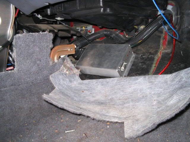 Hard to see from the pic but this is under the passenger side dash and the wires are running under the center console to the driver side of the dash. The communication wire on the other side of the box goes to your laptop. I then found a spot on the firewall to run my wire harness through. I had previously drilled a hole on the driver?s side just left and above the accelerator for my S-afc. I just bored that out a little to accommodate the larger harness. I also pulled my battery at this point for ease of access and safety. Wherever you drill through, just be sure that you have no obstacles on either side. It would suck to drill through your brake line or electrical harness. Don?t worry about the wires being behind the accelerator arm (in the pic). I managed the wire after I took the pic (I took a side angle pic because of space). 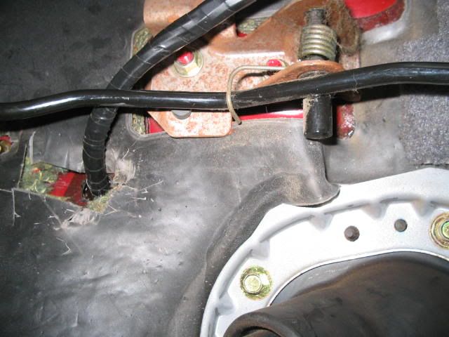 As you can see I also wrapped my harness wires up with electrical tape. It?s the way I?ve done it for years. You can, of course, use any pretty, multicolor wire wraps that you so choose. You can also put a grommet in the hole before you run your wires (helps seal out water). I used silicone window seal on the outside (works great on my window installs) I also ran my vac line through the same hole but didn?t get a pic of that. I used a hardline that I had off a ?donor? car. You can certainly use a soft line, just be careful you don?t get any crimps or cuts as you pass through the access hole. There is a nipple on the MSnS box that you attach it to. INSIDE ENGINE BAY Now, out of the car and into the engine bay. I laid out and quick taped the wires for now. 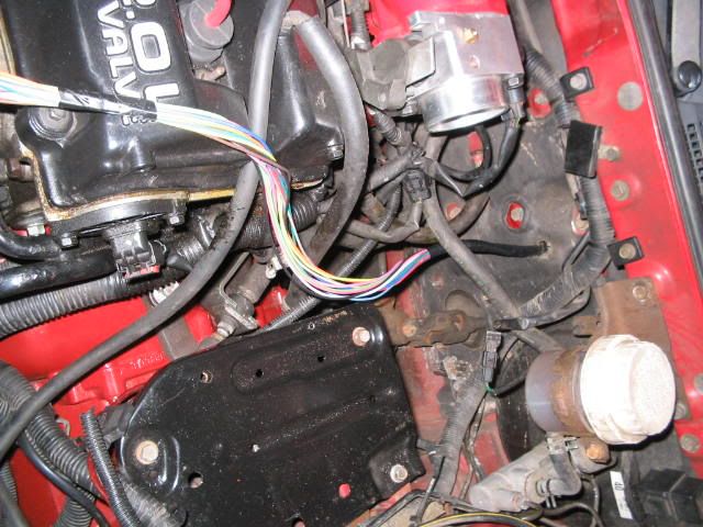 I will distribute and manage them later. First I want to install the 2 sensors (coolant temp and air temp). I started with the air temp sensor. You can either drill and tap a spot for the sensor (please do that with the intake OFF the car. Don?t want chips and shavings in the intake) or use an existing hole. I used an existing hole. But I did a little mix and match to make it work without drilling. This is a pic of the back of an intake manifold off a different vehicle. 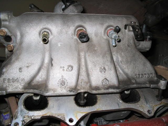 The large single outlet to the left (closest to the TB side ? remember this is the back of the intake mani) is for your brake booster. I took that one out and got some matching plumbing from home depot to make it into a T fitting. On one side I plugged in the brake booster hose and on the other side I plugged in the vac line from the MSnS (the hard line that was sent through the firewall and plugged into the nipple on the MSnS box). Then on the other side of the intake (next to the stock map sensor) there is a 3 way nipple (one line goes to the cruise control, one line goes to EGR and one line goes to the evap?). I took this one out and replaced it with the MSnS air temp sensor. (I want to make note here that I used Teflon tape for the sensor and the T-fitting. I have had very good luck with doing it this way). Here are a couple of pics of the sensor and fittings installed; 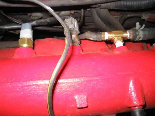 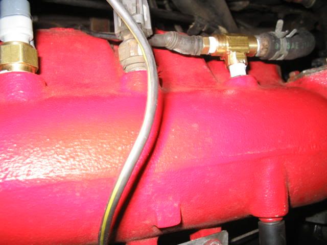 From here I went to the coolant temp sensor. Because I was retaining my stock coolant temp switch I needed to make a T-fitting. This way, I could mount both, using the existing opening. So I went back to Home Depot to get the correct fittings to make a T out of the existing hole (OK, that?s a little bit of a lie. I already had fittings kicking around, but if you don?t, THEN you can go to Home Depot to get them). In order to put this on, I had to pull off the thermostat housing so that I could have access to swing the T-fitting. Here is a pic of the T-fitting done with sensors (no T-stat housing). The MSnS sensor is on the front, while the stock sensor is off to the side; 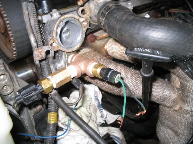 (a couple of things to point out here) It does look a little goofy and I honestly did not like how it came out (aesthetically). You are welcome to come up with better/shorter fittings or the like. If you care to pull off the housing (and have the drill bits and taps etc. needed) you can do it like I did another one: 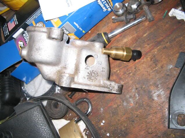 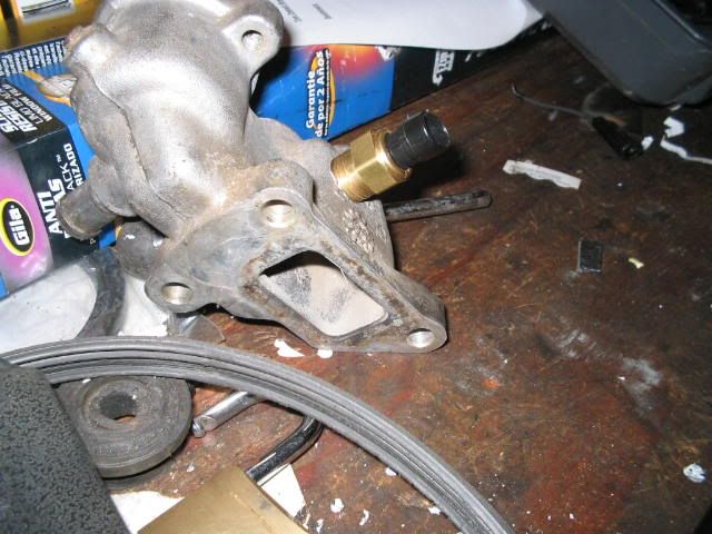 You can see that it is a much ?cleaner? look. Definitely looks more professional. Just be careful where you drill and tap through. You can see in this pic that the end of your sensor may have interference. 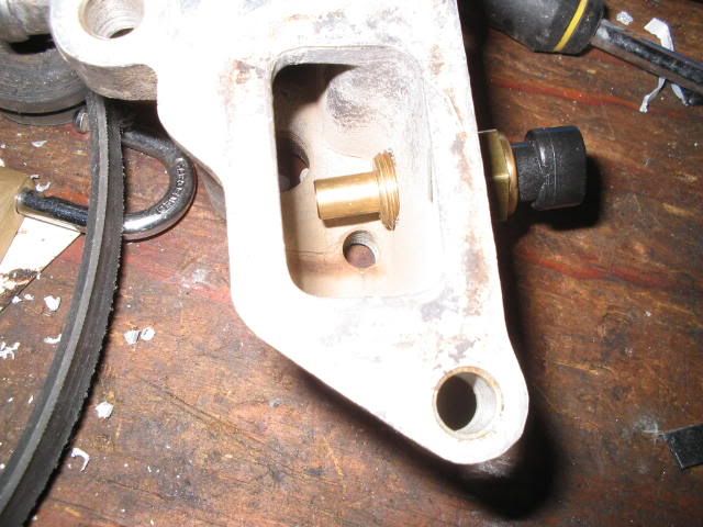 As for the ?non drill/tap? way, I did wonder if it would work properly with that T-fitting sticking out by itself and possibly not getting the proper flow. Don?t worry about it. It does work fine. Also, make note of the direction that the T goes in. If I turned that T in (so that the sensor would be right over the exhaust mani) then I?m thinking that it would generate an accuracy problem (with the heat from the mani rising up). As it is, the set-up that I have now comes close to matching my coolant temp gauge (a little lower but I always knew that the temp read high on my gauge). The only other part that was a component install was my wideband. I used the Innovate PLX. I drilled a hole in my downpipe and welded a bung in (being aware of any obstacles that the O2 sensor may hit). PICTURE HERE I then screwed in the sensor. PICTURE HERE I only use the wideband when I am tuning so, I have a block off for the bung when I am not using it. ENGINE BAY WIRING First off, keep in mind that some wire harness colors may be different from harness to harness. Check with the supplier?s schematics to verify the colors. Also, I soldered my connections to be sure that there was no interference (at first, I set up quick connectors for the injector harness and coils because I could then just unplug them to go back to stock for emissions purposes. I didn?t like it so I just soldered the connections) Now it?s time to start distributing and hooking up wires. The first thing I did was pull out the four wires (blue, pink, brown and orange) that I was not going to use (they are there for fuel pump - orange, fast idle - pink, fan control ? brown, and pin 31 wire ? dark blue; which I?m not sure what that is used for) because I am still running things off the stock ECU (i.e. fuel pump and fan control). We don?t have a fast idle set up, so this was unnecessary. I wound them up and taped them off in the engine bay for the possibility of future reference (I obviously took this pic after the install). 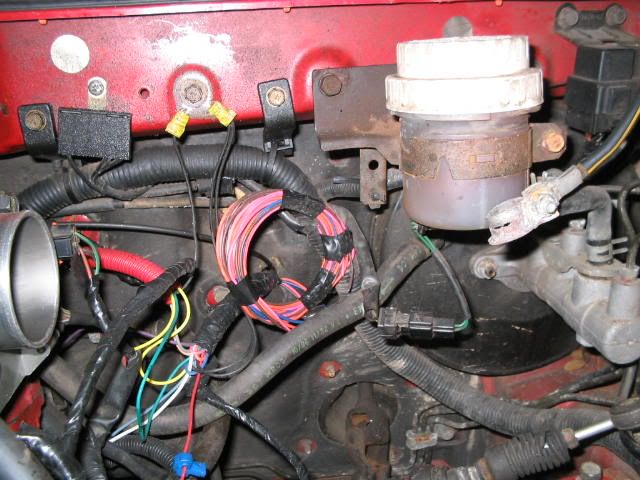 I took the other wires and laid them out to various positions (depending on where each was going). I tucked the wires that ran behind the intake manifold into a red wire management loom to make it look ?nifty?. 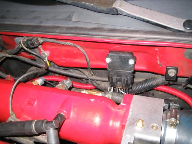 Don't mind the 4g63 ignitor mounted in front of the loom. I'll get to that later COOLANT TEMP SENSOR I then pulled the (MS) tan wire out to the coolant sensor and soldered it to the green wire of the sensor switch (the ?feed? wire for the switch). That left the black wire of the sensor(the ground), which I soldered to a ground wire (that goes back to a body ground) 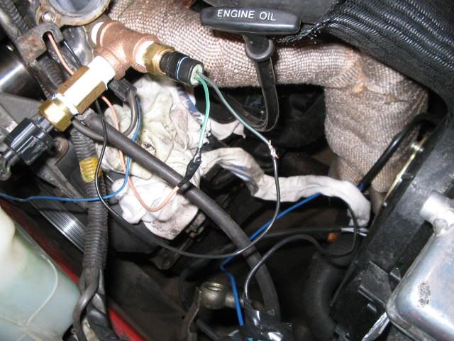 WIDEBAND In that same area of the engine bay, I ran my wideband wire (MS) grey. It is curled up inside my red wire loom until I need to use it. You can see it curled up in the upper left hand corner of this pic: 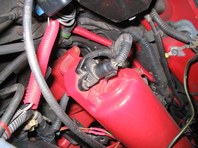 With my wideband in, I just uncurl it from the loom and hook it up to the wideband. AIR TEMP SENSOR Working our way back, it?s time to connect up the air temp sensor. I pulled the (MS) dark green wire out of the loom and soldered it up to the blue/black wire on the air temp sensor (again, the ?feed? wire). I then soldered the red/black wire (off the sensor, the ground wire) to a ground wire (the same ground wire as the coolant temp sensor). 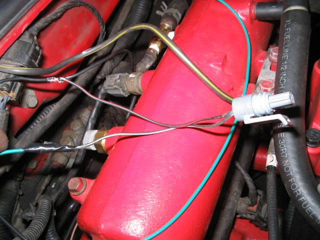 The blue/black wire off the sensor looks white in the pic (I don?t know why. Just lighting) but it is actually a blue/black wire that goes to the dark green of the MSnS. TPS That brings us to the TPS (throttle position sensor). On this sensor, we had to ?tap in? (connect up the wire while still maintaining a connection for the original wire). So I pulled the (MS) yellow wire from the loom and then I stripped back a small section of the brown/red wire (the ?feed? wire) off of the TPS. I then wrapped the (MS) yellow wire around that and soldered the connection. It?s a little tough to discern with the flash but here is the pic 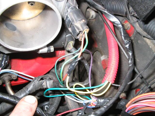 CRANK ANGLE SENSOR Now for the crank angle sensor (located on the back side of the block). Not too much fun soldering this connection. I took the (MS) purple wire out of the loom and ran it back down to the plug. This is also a ?tap in? situation. I had to strip off a bit of the blue/white wire (the ?feed? wire) that went to the sensor plug and wrap the (MS) purple wire around it. I then soldered that connection. Again a tough shot with the flash from underneath (the purple wire coming down looks white but it is purple) but it is effective enough. 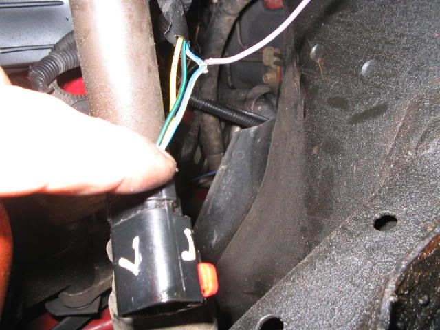 I then plugged her back in. INJECTOR HARNESS I unplugged the stock injector harness and pulled the whole injector harness off of the car. I put it in storage for emissions? use later on. I just left the plug on the car wiring harness in its place. You won?t need it (until emissions J). I took the (MS) green wire (for the 1 + 3 injector) and soldered it to the matching green wire on the replacement harness supplied by Terry?s kit. Then I took the (MS) violet wire (for the 2 + 4 injector) and soldered it to the matching violet wire on the harness. The third wire in the harness is the red power wire. I hooked that up to a 5 amp in-line fuse and line (yellow line coming off the red in the picture) and sent it to the power source (which I will talk about later). 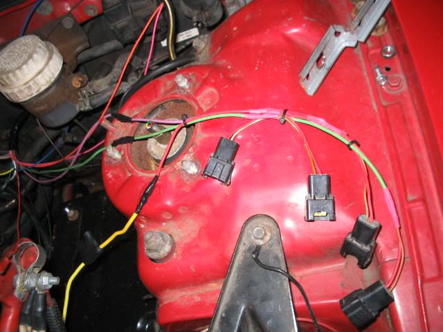 I then plugged in the harness to the injectors. 4G63 IGNITOR INSTALL I used the stock 4G63 mitsu ignitor for my spark. You can check out this thread (http://forums.2gnt.com/dcboard.php?az=show_topic&forum=54&topic_id=776&mesg_id=776&page=) for more info and identification of the wires on the ignitors (and the 5 pin vs 7 pin set-up). I used the 7 pin ignitor. I first located it on the firewall with self tappers; 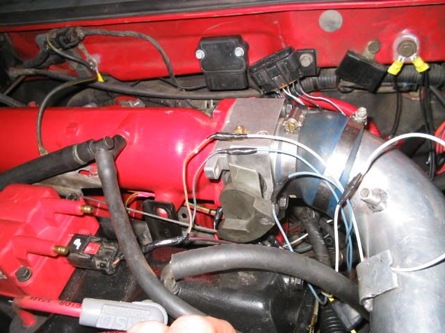 ( you might want to read through this next section a couple of times first, because it is a little confusing to just read. It?ll make sense after a while. I also found out through another install that the wires coming out of the stock ignitor harness are not always the same color/code. You should follow the markings on the ignitor itself )Then I needed to wire it in. First I identified the wires I was not using (white w/silver ring marked TAC on the ignitor and black w/white stripe marked VB) and cut them back. Then I pulled the wires from the MSnS loom that I needed (light blue for the 1 + 4 coils and white for the 2 +3 coils). Since these came out of the MSnS box they needed to be routed INTO the ignitor and then OUT TO the two coils. I soldered the (MS) white wire (for coils 2 + 3) up to the IB2 input of the ignitor (brown/red w/white ring). I then ran a wire (white wire for consistency) from the ignitor outlet marked Oo2 (blue w/white ring wire) to the connector for the 2 + 3 coil (brown wire on the coil connector). I then soldered up the 1 + 4 coil input/output. I used the (MS) light blue wire from the MSnS box and soldered it to the black w/silver ring wire that went to the IB1 socket on the ignitor. Then to send the signal back out, I soldered a wire (light blue for consistency) from to Oo1 socket (black/white w/silver ring) to the blue/black wire on the coil connector (wire for coils 1 + 4). That left just one socket; the GND socket (for the ground). I ran a black wire off the black w/white ring to a separate ground. I used this ground for ONLY the ignitor so there would be less chance of interference. Here is a pic of the set-up un plugged (with wires showing. Note the two wires clipped that are unnecessary); 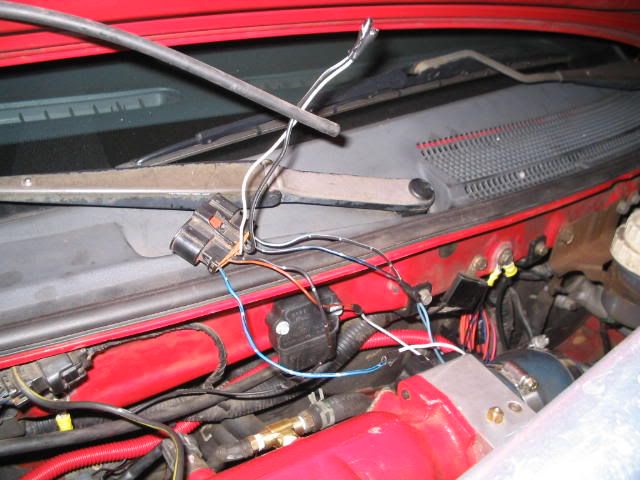 And here is a pic of the ignitor plugged in (note the yellow circle connector bolted to the firewall on the left, is my separate ground for the ignitor. I also soldered those connectors on);  COIL CONNECTOR We may as well go over the connector for the coil now (since we already connected up two wires to it in the previous ignitor section; the white to brown ? coils 2 + 3. The light blue to blue/black stripe ? coils 1 + 4) The only wire left is the power wire (red/black wire) in the center of the connector. Just leave it alone. Here is a pic of the connector;  or; 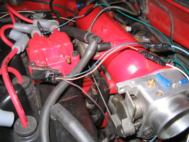 GROUNDS AND POWER WIRES Grounds I have already talked about how the grounds were hooked up and sent on three different items; the Coolant temp sensor, the Air temp sensor and the Ignitor. I talked about the Ignitor being hooked up to it?s own ground (see pic, left of ignitor)  For the two sensors, I soldered the two ground wires together into one and tucked them into the red wire loom. I then connected them to a ground (pictured below, to the right of the Ignitor) 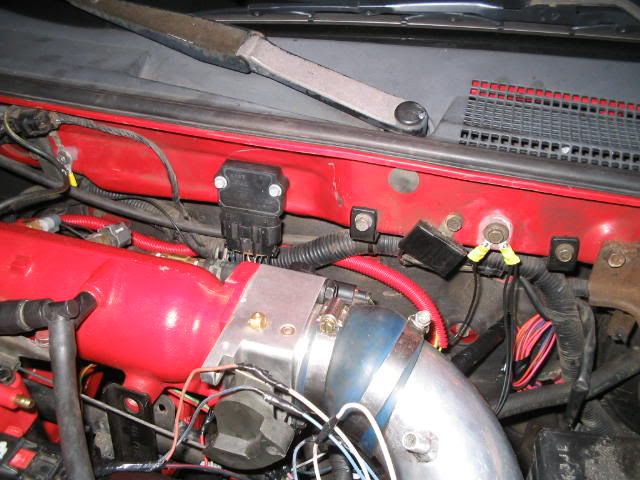 You can see the two circle connectors (which are also soldered on) connected up to the same ground. The connector that is positioned to the left is the ground for the two sensors I just discussed. You will see another connector with two wires that come out to the right. These are the grounds that come out of the MSnS ECU (read on). In the wire loom of the MSnS you will find two black ground wires. I just connected them together and put it to the same ground. (the two connected to the right) You may want to separate them to different points (possible interference conflicts). Or you may even want to go directly to the negative side of the battery, your choice. I didn?t see a problem with these using the same ground. The only one that I wanted to isolate was the ignitor ground. Power wires I talked about soldering up a 5 amp fuse to the injectors for a power source (yellow wire)  You can see that the 5 amp fuse is not in the socket yet. I generally put them in last. I then sent that wire to splice in with the red power source wire for the MSnS (so the injector harness would have its own 5 amp fuse). That wire (which also has a 5 amp fuse on it) I then sent to a 12v relay that I mounted on my old air box housing. 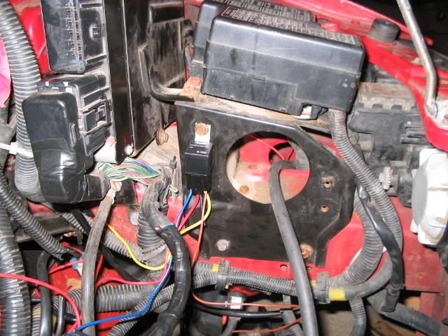 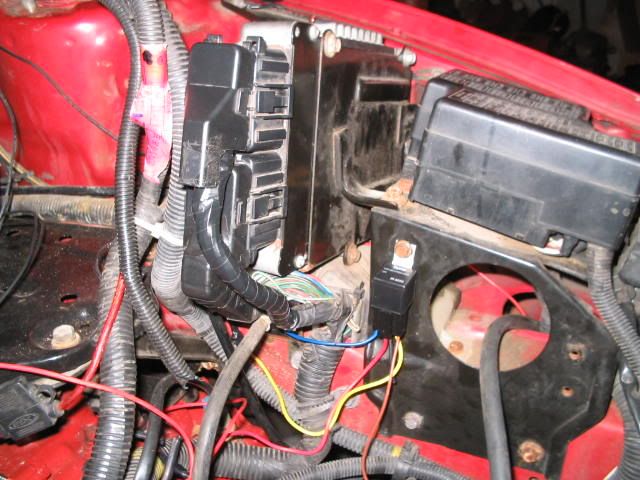 It's a little confusing here because I didn't take many explicit pictures for this (my bad). The red wire that is coming from the engine to the relay is the one that comes from the MSnS ECU and it has the injector harness tapped on to it. The big yellow wire coming out of the relay is a 20amp fuse (in-line) that goes directly to the battery. The brown wire, in this case, is the ground. That leaves only the blue wire unaccounted for (at the moment). So of the 4 wires at the relay; one is for the MSnS power(red, spliced to the injector harness with a 5 amp fuse in line for just the injectors), one is from the battery (yellow, with a 20amp fuse in-line), one is the ground (brown, which you can see where I grounded it right below the relay), and the last (the blue) is a very important one. That one is the wire for the ignition. That has to be a wire that powers up when your ignition is in run or start. You can search for a wire of your choosing that does that, but I just used the appropriate wire off the ECU (the one that the stock ECU uses). It is a black and white wire that is in position B20 off the ECU plug (at least for the 96 and 97. You should always check the wire with a tester, just to be sure). In addition to these wires and hook ups, there is one more fuse that should be put in. On the red power line to the MSnS box itself (between the injectors "tap in" and the MSnS box itself), there should be an in-line 2amp fuse spliced in. This will help protect your box from crossed up wires and spikes. Below I have included a general schematic to follow. I am not positive on the source but I have seen it on various sites on the web (including this one).The wire colors aren't necessarily correct but this will help in identification and understanding. 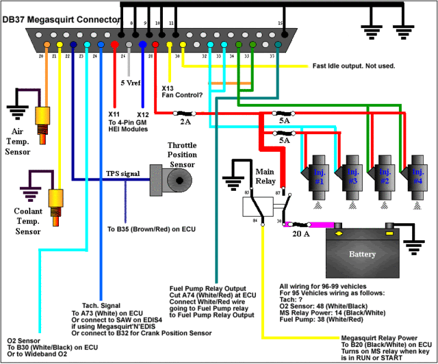 That?s the ?install? part of the MSnS in a generic sense. When you are done it may look something like this; 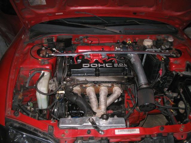 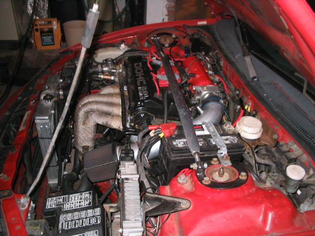 Just a reminder that wire colors may be different and you should think about where each wire is coming from and what it is doing, so that you will understand if some wire colors are different. From here, it is time to hit the computer and start the download/tune process. That I?ll leave up to another write up. Thanks, again, to Terry, Paul and Darin for your help in this project. written by bullettdsm Megasquirt |
| Document statistics: Last modified on 2011-05-31 21:07:18 by Corbin |
